DIY PEMF can save you money and even replace many of the machines available on the market. Also, building your own machine can help educate you about how PEMF works. Furthermore, you will get a better understanding of what it takes to make a PEMF device. Likewise, you will see how some machines can be very expensive because of all the marketing and business costs.
Today, we can ignore all of the extra costs and just concentrate on making a DIY PEMF machine. Actually, it is pretty easy to make a simple device that will emit pulsed electromagnetic fields. You can probably find all the needed tools in your junk drawer. However, you will need a soldering iron to complete this device. All it will take is a little time and you will be getting similar results to machines costing thousands of dollars.
Basically, this is a simplified how-to for people with a little DIY experience and understanding of electronics. However, as you follow along you may notice that it is easy enough to do for almost anyone. Most importantly, there are dangers such as being electrocuted or burned. Please be careful and observe the directions and warnings for the individual products.
OK let’s make a DIY PEMF device!
There are two basic types of PEMF devices. Most high output machines use powerful transformers and big capacitors to produce a big spark. The result is a square wave charge that delivers powerful treatments you can actually feel pulsing though your body. Our MegaPulse is this type of machine. Alternatively, PEMF’s can be produced with a digital waveform generator and amplifier. StemPulse and Sedona Pro work this way.
PEMF Controller Module
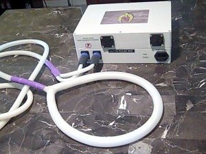
The machine we are displaying here uses a digital waveform generator and amplifier. Simply, we purchased the components on Amazon and screwed them together. From the image above, you can see the screw terminals for attaching wire. Everything is clearly marked. Literally, it will take less than a half hour to clip some wires and insert them into the connectors and tighten the screws.
Make sure the 12 volts from the transformer is attached with correct polarity to the waveform generator and amplifier. Then, attach the output from the waveform generator to the input of the amplifier.
The Transformer
We used some little 2 amp transformers when we first tested this device. They worked OK but they heated up very quickly and we knew they wouldn’t last. The transformer we chose is capable of 15 amps at 12 volts. That is about twice the amount it takes to power the 100 watt amplifier in our machine. Originally, it came with a automobile cigarette lighter socket and we just clipped it off and inserted the bare wires into the other components. Interestingly, this indicates you could run this DIY PEMF mat from your car lighter socket but it will really stress your car’s electrical system. We recommend against this without further testing.
The PEMF Mat
 Many DIY devices you see on the internet just use a simple coil to get a PEMF signal. At ElectroMeds, we ALWAYS aim for the top! Likewise, building a mat to test our controller is the only way to go. Also, we want the mat to have some qualities which are not available on other mats.
Most mats fold and still take up a lot of space. We want our mat to be thin and flexible so it can be rolled up. Unfortunately, this creates a problem because the thin copper wire used in PEMF mats can wear out and break. We solved this problem by using multi-stranded and PVC insulated copper wire sandwiched between very thin yoga mats.
The mat coils are wound according to Nikola Tesla’s patent for efficient electromagnetic coils. Also, the coils are wound in a square pattern so the PEMF’s reach the edges of the mat. You can see there are more turns where your feet would go if laying on it. Generally, this is the way most mats are made. Typically, your feet get more free PEMFs from the Earth and most treatments recommend lighter doses for your head. This mat design reflects those observations.

To wind the coils, we calculated 3 progressive lengths of wire and unwound them down our long driveway. Then the first yoga mat was laid out and sprayed with super strong contact cement. Each length of wire was folded double then carefully pressed into place on the tacky mat. Then, the wires were cut and soldered together to make the Tesla style array. Finally, more contact cement was sprayed on and the second yoga mat laid on top. Once the coil ends were screwed into the controller terminals we had a working PEMF machine!

Testing the DIY PEMF Machine
 Of course, we used DIY test equipment to test our DIY machine. We found a little DIY oscilloscope online and used that combined with coils from a StemPulse to test the output. Interestingly, electromagnetic waves create electricity just as electricity creates electromagnetic waves. We used that concept and our little test rig to prove our DIY PEMF machine works.
Specifically, we measured for the presence of electromagnetism near and far from the mat. We were able to measure ambient waves and then a much stronger field near the mat. Also, the field extended to the edges of the mat and were quite powerful 7 or 8 inches from the mat. It seems the coil design helped make a robust energy field that may penetrate deeper than first expected.
To conclude, we are very excited for this project and happy to share it. Of course, we have tried this machine on ourselves and it has worked to remove pain from injuries such as sprained wrist and tennis elbow. Conversely, there is more work to do in measuring the output properly and making improvements. Please let us know if you build your own DIY PEMF and what your results are.
List of products we used to build our DIY PEMF:
Diymore TPA3116DA DC 12V 24V 100W Mono Channel Digital Power Audio Amplifier Board TPA3116D2 Large Capacity Board Amazon 13.99
Frequency Generator, DROK DC 3.3V-30V 5-30mA 1Hz-150kHz Adjustable Output PWM Pulse Duty Cycle Square Wave Function Signal Generator Module Amazon 13.99
AC to DC Converter, RoyPow 180W (Max 200W) 15A 100V~120V to 12V Car Cigarette Lighter Socket AC/DC Power Supply Adapter Transformer for Inflator, Car Amazon 34.47
(2)Sunny Health and Fitness Yoga Mats (Blue) amazon 59.19
DSO138 Oscilloscope, DSO 138 DIY Mini Oscilloscope, 2.4″ TFT 1MSPS Digital Oscilloscope Kit Handheld Pocket Sized 13803K (Welded Version) Amazon 24.88
Diymore DSO138 Oscilloscope Case DIY Kit 2.4″ TFT Digital Oscilloscope Acrylic Case DIY Kit Acrylic Shell DIY Kit Amazon 11.50
Onyehn XR2206 High Precision Function Signal Generator DIY Kit Sine/Triangle/Square Output 1Hz-1MHz Adjustable Frequency Amplitude + Transparent Case Box Shell amazon 9.99
MTW hook-up wire, 20 AWG, 10-stranded, bare copper, black insulation, 600V, 500ft spool. Alternate part ID: 029892335939. automationdirect.com 29.75
(2) 3M 17.6 oz. Hi-Strength 90 Spray Adhesive 25.96
Note: we didn’t put active links here because they may change within Amazon’s shopping application. Copy/paste the products into the search bar at Amazon and you should be able to find these products quite easily. Happy hunting!
MultiPulse

Pocket Sized - Unique and Highly Advanced Features
Sedona Pro and Pro +

State of the art design, usability and professional performance
MegaPulse


Can you provide the measurements for the wire coils?
Hi Jonathan,
We just did the math and bought a large spool of wire that would be about 4ohms resistance to match the class D amplifier. The mat is about 2 feet by 6 feet. We approximated the coil variance for the different length coils. Actually, we are not sure it works as planned or even makes a difference. Surely, more wire means more electromagnetic force. Arguably, three coils in series with different resistance measurements will create different voltages at the start of each coil. Hope this helps
How many Gauss or Teslas does the put out?
Hi Nathan,
Simply, we are not sure. We did some calculations and found the 100 watt amplifier may draw as much as 8 amperes. You can feel the field with your hand. Also remember, power is “energy x time” so it depends how long you are using the mat.
Where does the DROK signal generator connect to? Also, what is the difference between the DROK and Onyehn XR2206? Also, is there a max frequency the square wave should not exceed?
Correction: Power is Energy per (divided by) time, not Multiplied by.
Re: How many Gauss or tesia? I saw this mat a few months ago and so impressed, I had to build one myself. You can estimate the on axis B-field of an N-turn spiral by calculating the B-field of an N-turn loop with radius equal to r-average of the spiral. Assuming both pushing the same ELF current I.
I built a spiral mat after reading this a few months ago. What I found is that it is very directional-really high gain at the center. want to know how strons the field is? Connect your mat/coil to a DC pwr supply and connect an Ammeter (Use your multimeter if the pwr supply doesn’t display current.) in series. Slowly increase the voltage from zero until the current equals one Ampere.
You can use your smart phone to measure the magnetic field. For Android I use Magnetomer or ultimate EMF Detector Pro. I’m sure iphone has something similar.
That’s it. If you double the current you double the magnetic field strength.
I hope this helps.
How do you keep the huge back EMF current spike generated by the inductor from destroying your power amp after a pulse ?
I’m sorry but the person who wrote that article is no longer with our company. Hopefully you can find the answer elsewhere.